One of the key advantages of the Raspberry Pi is its GPIO interface, which adds significant flexibility for a wide range of hardware projects. Due to its importance, it also plays a critical role in debugging.
Each GPIO pin can be configured in one of seven modes, defining its behavior:
INPUT– Reads the current signal level (HIGH or LOW)OUTPUT– Sets the output voltage levelALT0–ALT5– Assigns the pin to specific hardware functions (e.g., UART, SPI, I2C)
Configure GPIOs Link to heading
When taking a looking at the BCM2835 Peripherals on page 102 we can find a list of all 5 alternate functions.
Our goal for now is to get UART functioning via the GPIOs so we can debug our hardware.
The documentation says that the Alternative Function 0 of GPIO14(pin 8) and GPIO15(pin 10) are TXD0, meaning Transmit Data and RXD0 meaning Receive Data. That is exactly what we need, we’ll just have to
configure the GPIO14 and GPIO15 to use Alternative Function 0.
Section 6.1 in the BCM2835 Peripherals comes with a new register layout for configuring our General Purpose I/O. The first few registers in the list already sound like what we need.
| Address | Field Name | Description | Size | Read/Write |
|---|---|---|---|---|
0x3F200000(Per: 0x7E200000) |
GPFSEL0 | GPIO Function Select 0 | 32 | R/W |
0x3F200004(Per: 0x7E200004) |
GPFSEL1 | GPIO Function Select 1 | 32 | R/W |
0x3F2000..(Per: 0x7E2000..) |
GPFSELn | GPIO Function Select n | 32 | R/W |
0x3F200014(Per: 0x7E200014) |
GPFSEL5 | GPIO Function Select 5 | 32 | R/W |
Each GPFSEL register comes with 32 bits. Each block of 3 bit, starting with the least significant bit, configures the functionality of a GPIO pin:
| Bits | Function |
|---|---|
000 |
GPIOn is an input |
001 |
GPIOn is an output |
100 |
GPIOn takes alternate function 0 |
101 |
GPIOn takes alternate function 1 |
110 |
GPIOn takes alternate function 2 |
111 |
GPIOn takes alternate function 3 |
011 |
GPIOn takes alternate function 4 |
010 |
GPIOn takes alternate function 5 |
In 32 bits we can fit $\lfloor 32/3\rfloor=10$ possible GPIOs starting from least significant bit(in little endian). Meaning the highest 2 bits will stay empty.
GPFSEL0 → GPIO0 - GPIO9
GPFSEL1 → GPIO10 - GPIO19
GPFSEL2 → GPIO20 - GPIO29
GPFSEL3 → GPIO30 - GPIO39
GPFSEL4 → GPIO40 - GPIO49
GPFSEL5 → GPIO50 - GPIO53 !This register only has 4 GPIOs !
Setting GPIO-14 and -15 to ALT0
Link to heading
Now we can configure the registers in such a way that GPIO14 and 15 use ALT0.
    const GPFSEL1: u32 = 0x3F20_0004;

    let current = core::ptr::read_volatile(GPFSEL1 as *const u32);

    let mask = !(0b111111 << 12);
    let cleared = current & mask;

    let new_val = cleared | (0b101101 << 12);

    core::ptr::write_volatile(GPFSEL1 as *mut u32, new_val);
Lets understand what happens:
- We read the current state of the register because we don’t want to override other configurations.
- We create a mask by converting all bits to
1except the6bits that make out FSEL14 and FSEL15. (Function Select = Term used for the 3bit segments) - We
ANDthe mask with current state keeping all bits in the same state except the 6bit we want to change. - Set the area we just cleared to
0b101101(Alt0code twice) - Write back to the register
Hardware Link to heading
The software part is over. Next is connecting to our computer and listen to the output.
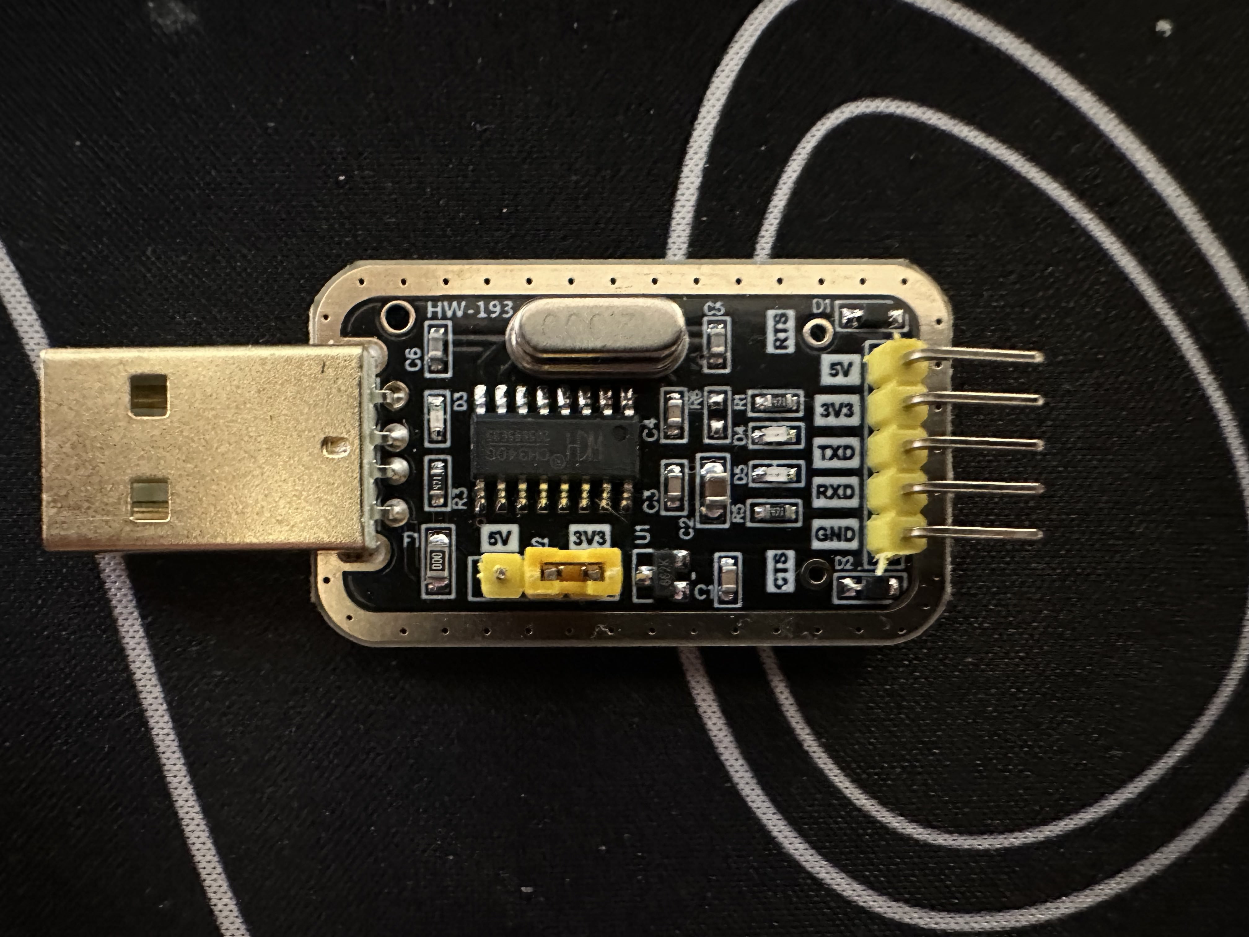
For this we need a UART TTL to USB converter.
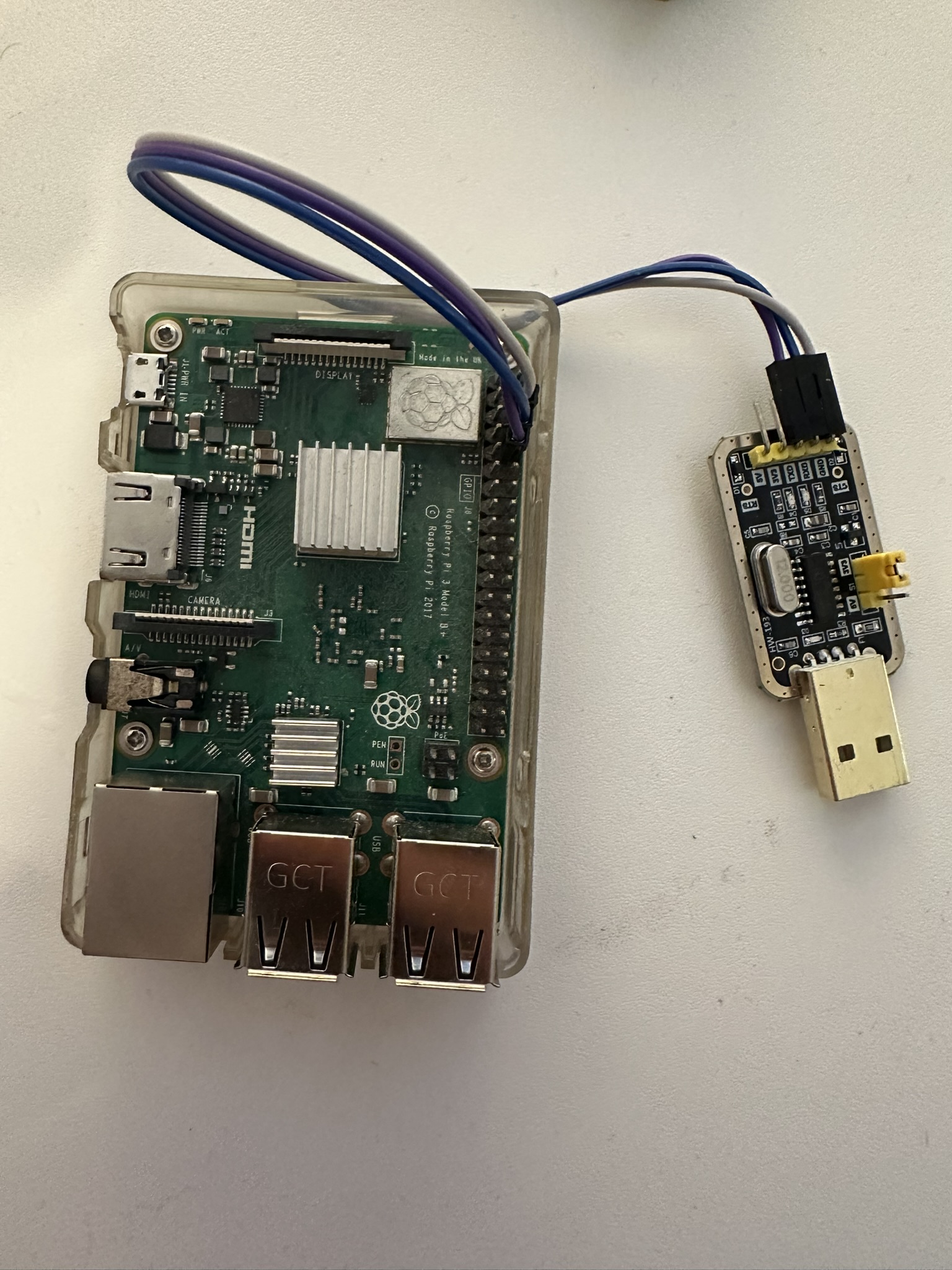
Then we will connect it to our PI via 3 jumper cable. GND to GND, TXD to RXD and RXD to TXD.
With the following command we can read the output:
screen /dev/tty.usbserial-3110 115200
Hello World!
Hello World!
...
/dev/tty.usbserial-3110 could be called differently
Additional Code Link to heading
Following code would makes the process of changing GPIO function cleaner:
#[repr(u32)]
const GPFSEL_BASE: u32 = 0x3F20_0000;

pub enum GPIOFunction {
    Input = 0b000,
    Output = 0b001,
    Alternative0 = 0b100,
    Alternative1 = 0b101,
    Alternative2 = 0b110,
    Alternative3 = 0b111,
    Alternative4 = 0b011,
    Alternative5 = 0b010,
}

pub fn set_gpio_function(gpio: u8, state: GPIOFunction) -> Result<(), &'static str> {
    let register_index = gpio / 10;
    let register_offset = (gpio % 10) * 3;
    let register_addr = GPFSEL_BASE + (register_index as u32 * 4);
    unsafe {
        let current = core::ptr::read_volatile(register_addr as *const u32);

        let mask = !(0b111 << register_offset);
        let cleared = current & mask;

        let new_val = cleared | ((state as u32) << register_offset);

        core::ptr::write_volatile(register_addr as *mut u32, new_val);
    }
    Ok(())
}