While doing some research about how to implement interrupts for my Raspberry Pi 3b+ kernel project I’ve come across the topic of Exception Levels.
Exception Levels are a way to allow or disallow the running process to access certain registers. The ARMv8-A architecture has defined that there are 4 levels. From EL0 which is the most restricted level to EL3 which has the most rights. The ARM Reference Manuel doesn’t specify what application should run on which Exception Level but gives a rough idea what they may be used for.
| Exception Level | Usage |
|---|---|
| EL0 | User Space(Applications) |
| EL1 | Kernel/OS |
| EL2 | Hypervisor |
| EL3 | Secure monitor/firmware |
It’s also specified that EL2 and EL3 are optional that means that a company like Broadcom may just leave that feature out because they may not be required for that specific use case, or just reduce the feature size like not implementing ARM TrustZone.
Exception Link to heading
Before we go deeper we need to clarify what an exception is.
An Exception is a general term used for different types of events that may require the CPU to process them before continuing the normal workflow.
These are a few types of exceptions that can occur:
- Interrupts (IRQ/FIQ) -Interrupt Requests(IRQ) can be thought of as a GPIO or timer interrupt
- Synchronous Exception - A synchronous exception may be an invalid memory access
- System Errors
Behavior during an exception Link to heading
After an exception gets triggered the CPU stops in its tracks and tries to resolve the exception before it can resume execution. There are two rules that get important while resolving an exception:
- On taking an exception, the Exception Level can only increase or remain the same.
- On returning from an exception, the Exception Level can only decrease or remain the same.
Stack Pointer Registers Link to heading
A stack pointer as you may know tells the processor where to store stack data. To ensure that lower ELs don’t have access to higher ELs stack, the ARMv8-A architecture gives each Exception Level its own stack pointer.
SP_EL0- EL0SP_EL1- EL1SP_EL2- EL2 (optional)SP_EL3- EL3 (optional)
Each higher EL can choose to use its own stack pointer or that of a lower EL.
EL3 can use SP_EL3,SP_EL2,SP_EL1 and SP_EL0
EL1 may only use SP_EL1 and SP_EL0
Exception Link Registers Link to heading
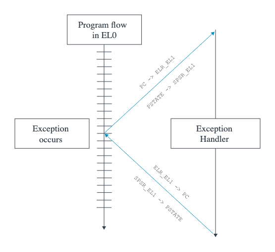
Before the Processor jumps to the function that will resolve the exception it has to remember where it left off.
That is the job of the Exception Link Registers(ELR). As soon as the exception returns the processor will return to the address stored in ELR_ELn.
Here we have to keep in mind that there are only three ELR_ELn registers: ELR_EL1, ELR_EL2, ELR_EL3
EL0 can not directly handle any exceptions on its own so it is required to use ELR_EL1. Any other Exception Level 1-3 can use itself to handle the exception or use a higher Exception Level.
Simplified divide by 0
- A process in
EL0divides by 0 - CPU triggers a synchronous exception
- CPU saves current address to
ELR_EL1 - CPU switches to
EL1 - CPU checks the
vector_tableand jumps to thesynchronous exceptionoffset - Exception handler resolves the issue and returns with a down grade to
EL0 - CPU continues process at
ELR_EL1
SPSR and PSTATE Link to heading
I’ll not go to deep into these registers but they are also a important part before the exception handler takes over.
The PSTATE register can’t be read directly and has a few special purpose registers to allow the system to read the values. It stores data like the Carry Condition flag or Negative Condition flag.
Before jumping a “backup” of this register is made and saved in a SPSR_ELn register and restores it when returning from the exception handler.
Vector Table Link to heading
On each exception the CPU has to check where it has to jump to, to handle the exception here we can use the vector table.
Each Exception Level has a Vector base Address Register(VBAR_ELn) except EL0.
Depending on the Current exception level and exception type it may jump to different locations.
Offset table based on VBAR_ELn address
Link to heading
| Synchronous | IRQ or vIRQ | FIQ or vFIQ | SError or vSError | |
|---|---|---|---|---|
| Current Exception Level SP_EL0 | 0x000 | 0x080 | 0x100 | 0x180 |
Current Exception Level with SP_ELx (x>0) |
0x200 | 0x280 | 0x300 | 0x380 |
There are 8 more offsets but for the sake of simplicity I’ll keep them out and refer you to the Arm Architecture Reference Manual. They refer to the EL level immediately lower.
How does this work now? As soon as an exception is thrown it checks the vector table and depending on the type of exception uses a different offset.
a vector table may look like this in assembly:
vector_table_el1:
    /* Exceptions from EL0 */
    b el1_sync_el0
    b el1_irq_el0
    b el1_fiq_el0
    b el1_serror_el0

    /* Exceptions from EL1 */
    b el1_sync_current
    b el1_irq_current
    b el1_fiq_current
    b el1_serror_current
Reading the current Exception Level Link to heading
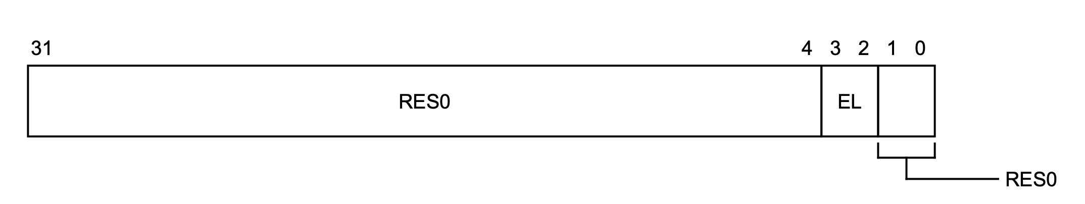
The CurrentEL register contains the information about the current Exception Level
mrs x0, CurrentEL
Or the rust equivalent:
let current_el: u64;
unsafe {
    core::arch::asm!(
        "mrs {el}, CurrentEL",
        el = out(reg) current_el,
    );
}
The Exception Level is stored in the 2. and 3. bit of the system register.
| Exception Level | bits(3,2) |
|---|---|
| EL0 | 00 |
| EL1 | 01 |
| EL2 | 10 |
| EL3 | 11 |
CurrentEL Memory Layout
From EL2 to EL1 Link to heading
This section focuses on how to drop down in Exception Levels with the focus on a Raspberry Pi, because that was the entire reason I went down this rabbit hole.
Lets start by defining a simple vector table EL1 will use to decide on where to jump.
 1.macro    ventry    label
 2.align    7
 3b    \label
 4.endm
 5
 6.section .vector_table, "ax"
 7vector_table:
 8    ventry .               // Synchronous            0x000
 9    ventry .               // IRQ                    0x080
10    ventry .               // FIQ                    0x100
11    ventry .               // SError                 0x180
12
13    ventry .               // Synchronous            0x200
14    ventry irq_handler     // IRQ(Interrupt Request) 0x280
15    ventry .               // FIQ                    0x300
16    ventry .               // SError                 0x380
We use a macro to align all entries in this table by $2^7 = 128 bytes$ because each offset is separated by 0x80=128.
The first 4 ventrys define the exception handlers for exceptions triggered in EL0, for my current purposes I’ll just leave them empty.
Line 14 we reference a function irq_handler which handles the exception and prints to UART, but this is not important right now for dropping in exception levels.
The basic idea of going down in exception levels is, that we pretend an exception happened and we want to return from it.
el2_to_el1:
    mov x0, #(1 << 31)
    msr HCR_EL2, x0
First we have to tell the CPU that the all lower exception levels shall run using AArch64. For that we have to set the RW bit in the HCR_El2 register (more information about this register can be found at page 2487 in the Reference manual).
el2_to_el1:
    mov x0, #(1 << 31)
    msr HCR_EL2, x0

    mov x0, #(0b0101)
    msr SPSR_EL2, x0
    //...
Now we set the SPSR_EL2 Register that contains information about the point where it left off.
As mentioned before: We are pretending that a exception has already happened. Normally the CPU sets all of these values by itself.
M[4], bit [4]: The 4th bit, in our case 0, tells the CPU that our fake exception was taken from a AArch64 context. Set it to 1 if you want to use the AArch32 context.
M[3:0], bits [3:0]: Bit 0-3, in our case 101 tell the CPU that our exception comes from a context where we used the EL1h state. EL1 meaning that we “came” from exception level 1 and h meaning that we used the stack from EL1.
    .stack 0x8008000 : ALIGN(16)
    {
    __stack_start = .;
    .+=0x10000;
    __stack_end = .;
    }
el2_to_el1:
    mov x0, #(1 << 31)
    msr HCR_EL2, x0

    mov x0, #(0b0101)
    msr SPSR_EL2, x0

    ldr x0, =__stack_end
    msr SP_EL1, x0
In the linker script we declared that the region from 0x8008000 to 0x8018000 should be the stack for EL1. Due to a stack growing downwards, meaning it starts at 0x8018000 and new data added grows in the direction of 0x8008000.
Now we just have to set the new stack pointer start address by setting it to __stack_end.
el2_to_el1:
    mov x0, #(1 << 31)
    msr HCR_EL2, x0

    mov x0, #(0b0101)
    msr SPSR_EL2, x0

    ldr x0, =__stack_end
    msr SP_EL1, x0

    ldr x0, =kernel_main
    msr ELR_EL2, x0
With ELR_EL2 we set the address where the processor should jump upon return. In this case it’s a function called kernel_main.
el2_to_el1:
    mov x0, #(1 << 31)
    msr HCR_EL2, x0

    mov x0, #(0b0101)
    msr SPSR_EL2, x0

    ldr x0, =__stack_end
    msr SP_EL1, x0

    ldr x0, =kernel_main
    msr ELR_EL2, x0

    adr x0, vector_table
    msr VBAR_EL1, x0
Here we set the start address of the vector table we defined earlier.
el2_to_el1:
    mov x0, #(1 << 31)
    msr HCR_EL2, x0

    mov x0, #(0b0101)
    msr SPSR_EL2, x0

    ldr x0, =__stack_end
    msr SP_EL1, x0

    ldr x0, =kernel_main
    msr ELR_EL2, x0

    adr x0, vector_table
    msr VBAR_EL1, x0

    eret
Last but not least we return the exception. Now the processor wants to return to the “previous” state it left of and goes into EL1 starting with the function kernel_main.